Single crystal data reduction
Single-crystal data reduction is performed in a series of steps:
peak search.
determination of the orientation matrix.
refinement of the orientation matrix and instrument offsets.
integration of the intensity for each reflection.
These steps are explained in detail below.
Peak search
The peak search consists of locating reflections on the detector. It is carried out with the program peakfind, which is accessible from the menu Single Crystal of the main window. peakfind locates voxels with counts above a certain threshold. It then groups these voxels into clusters. Two voxels belong to the same cluster if they are neighbors, and they are considered neighbors if they are adjacent in x, z, or frame dimensions. Once the clusters are identified, if the size of a cluster exceeds a given threshold, it is considered a peak, and its center of mass is assigned as its coordinates. As a final step, these coordinates are converted into Cartesian coordinates in reciprocal space, which will later be used for the calculation of the orientation matrix.
The peakfind user interface is shown in Fig. 10. In the upper part it displays a replica of the scan loader of the main window, that is used to select the scans to be procesed. If no scans are selected, peakfind assumes that all the scans in the list must be processed. The meaning of the input parameters of peakfind are explained below:
- Threshold
Minimum number of counts a pixel must have to be considered as a pixel belonging to a reflection.
- Minimum peak size
Minimum number of connected pixels with counts equal or greater to
threshold. This means that ifpeakfindfinds a cluster ofnpixels with counts equal or greater thanthreshold, butnis less thanminimum peak size, this cluster will not considered a reflection.- Box
Optional argument. If a box is defined, the peak search will be performed only within the box.
- Append
If this option is checked, results will be appended to previous results. Otherwise, previous files with the same
cfl namewill be overwritten.- Automatic search
If this option is checked, peaks will be determined automatically by
peakfind, according to the input parameters given by the user.- User list
If this option is checked, the coordinates of the peaks are given by the user. The coordinates must be provided in a file named
user.pks, located in theoutput directory. The format of this file is the following. The first line must specify the number of peaksnin the file. The following n lines must specify the coordinatesx,z,frameof the peak and thenameof the scan. The coordinatesx,z,frameare assumed to be numbered from zero, so they can easily estimated with the 2d viewer.- Automatic search + user list
If this option is checked, both
automatic searchanduser listoptions are applied.- Instrument file
Instrument file. If a project is open, the default value is the
geomfile of the project.- Output directory
Directory in which to run
peakfind. If a project is open, the default value is the directoryPeaksinside the project folder.- CFL name
Name of the
cflfile. This file is the input file forpeakfind.
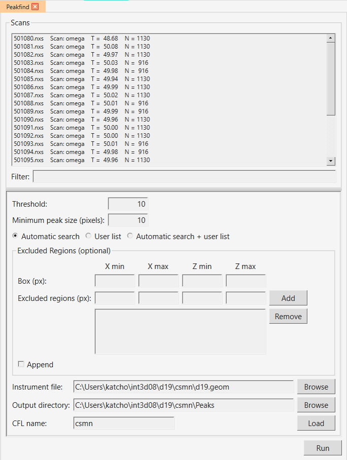
Fig. 10 User interface of peakfind.
Determination of the orientation matrix
Refinement
Integration
The integration provides us with a list of integrated reflections, i.e. a list of h,k,l indices together with their corresponding intensities. Single crystal data can be integrated with two different programs, int3d and racer. int3d is designed to integrate data from large area detectors, such as those of D19 and XtremeD, although it can integrate data for any 2D detector. On the other hand, racer has been used for integrating the data of small detectors such as those of D9 and D10 during decades and is the recommended choice for these two instruments. The user interface of these programs can be opened from the Single Crystal -> Integration menu.
Int3d
Racer
Racer can only be used for D9 and D10 instruments. Unlike int3d, it does not need a UB matrix to perform the integration.